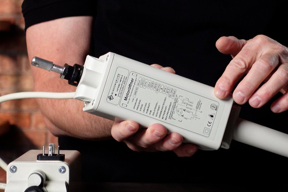
Spindle drives type JM: Explanation of the type key
We often receive queries about the type designation of our JM type drives. Therefore, I will give you a short list of the differences here. I do not limit myself to the "ending" in the type designation (i.e. 0, L, LS, LA, ...), but also go into the type code completely.
We distinguish in principle between two designs
- Round in aluminum housing (JM-) In the type designation, there is a hyphen after the first two letters
- Square in plastic housing (JM) No hyphen after the first two letters


The type of mounting
These actuators are at least always pivoted "at the top", i.e. at the end where the push rod comes out. Two bolts on the left and on the right engage in two blind holes on the actuator. You can see this quite well in the following pictures:


The distance between the two blind holes is either 54mm or 69mm. This is expressed in the third letter (for example: JM-A...., JM-B..., JMA... or JMB...). The "A" stands for 69mm and the "B" for 54mm.
Sometimes there is a fourth letter (A or B). If this is present, there is another attachment point at the bottom of the drive housing. Here are two examples:


Pluggable connector
If there is an "S" as the fifth letter, it means that the connecting cable has a plug (four-pin valve connector). Signaling contacts are not possible in this case. The advantage is easy maintenance in case of replacement of defective actuators.


Thrust
The thrust force is indicated in [N] separated by a hyphen. 9.81 N corresponds to 1 kilogram. As an approximation, divide the specified force by 10 to obtain the kilograms that this actuator can lift. The default value is 500N, but 700N is also possible.
It is also important to know that the tractive force of the drive can only be seen from the technical data of the drive. This is for example 150N or 350N.
Stroke length
The specification after the thrust is the stroke length, so as far as the push rod extends in [mm]. These actuators have a maximum stroke length of 500mm (round design in aluminum housing) and 300mm (square design in plastic housing).
Signaling contacts
The last letters indicate, among other things, signaling contacts. These do not necessarily have to be connected for operation. Often they serve as feedback for a building control system on the state of the window (open, closed).
-0 (round design)
This means that there is no signaling contact.
Switching off in the closed direction is performed by a limit switch, which must be actuated in the retracted state.
-L (round design)
There are two signaling contacts. These are potential-loaded, i.e. they output a voltage when the respective state is reached (open, closed). This voltage is of course no longer present when the actuator is no longer energized (the normal case).
Switching off in the closed direction is done by a limit switch, which must be actuated in the retracted state.
-LS (round design)
The actuator has a signal contact, which on the one hand is protential free (you can switch a separate voltage with it) and on the other hand reports only one unique state: "closed". Everything else (push rod is already extended 1mm) means open. So basically "not closed".
The shut-off in closed direction is done by a limit switch, which must be actuated in retracted state.
-LAS (round design)
The actuator has a signal contact, which on the one hand is protential free (you can switch a separate voltage with it) and on the other hand reports only one unique state: "closed". Everything else (push rod is already extended 1mm) means open. So basically "not closed".
In addition, the actuator has a mechanical load cut-off in the closed direction.
-LA (angular design)
The actuator has a signal contact, which on the one hand is protential free (you can switch a separate voltage with it) and on the other hand reports only one unique state: "closed". Everything else (push rod is already extended 1mm) means open. So basically "not closed".
In addition, the actuator has a mechanical load cut-off in the closed direction.
-EA (angular design)
The actuator has a signal contact, which on the one hand is protential free (you can switch a separate voltage with it) and on the other hand reports only one unique state: "closed". Everything else (push rod is already extended 1mm) means open. So basically "not closed".
Switching off in closed direction is done by a limit switch, which must be actuated in retracted state.
Overview of signaling contacts


Overview of limit switching in the closed direction
First of all: In the open direction, all actuators always switch off automatically via an internal microswitch.
In the closed direction, the limit switching is also performed either by a microswitch (in this case, the externally visible "button" must be actuated) or by an internal mechanical load disconnection.
If the drive has no load cut-off and is installed in such a way that the limit switch is not actuated, the drive will sooner or later overheat and become defective.


