Connection of a staircase SHEV control panel
In the 1st part we have introduced the single components of a staircase SHEV more exactly - what is needed to guarantee a functioning smoke removal. Read more here Basics of SHEV systems in staircases
This part of our blog post is about connecting the components discussed.
Basic requirements for the lines
The Line Installation Guideline (MLAR) specifies that you must install the lines to the drive, the SHEV control points and the smoke detector with functional integrity E30. Remember that a flush-mounted line does not automatically mean functional integrity E30.
230V supply to the control panel
Fuse the supply line to the SHEV control panel separately. The circuit should not contain any other consumers.
Connection of the drive
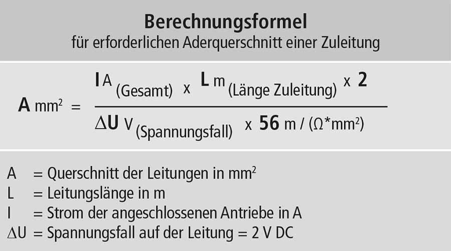
Here it is important to ensure that the cross-section of the cable is sufficiently dimensioned. For the EMB 7300 SHEV control panel, you will find a calculation formula for the cable cross-section in the installation instructions. Then multiply the calculated value by 3 (to be found in the cable diagram) and round up to a usual cross-section.
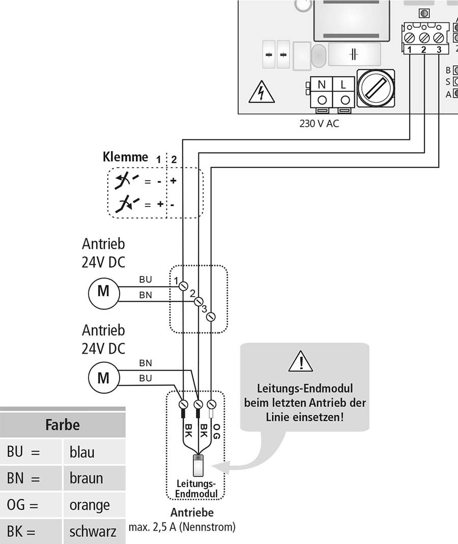
You need three wires, two of which (terminals 1 and 2) supply the voltage for operation. The return conductor, connected to terminal 3, provides line monitoring for short circuit or open circuit. A small current flows through the return conductor, the strength of which provides information about the condition of the line. For this to work, it is necessary to install the line end module included in the scope of delivery in the junction box at the actuator.
From time to time you can see these modules installed in the control panel. This is wrong and ensures that the line is not monitored.
Connection of fan pushbuttons
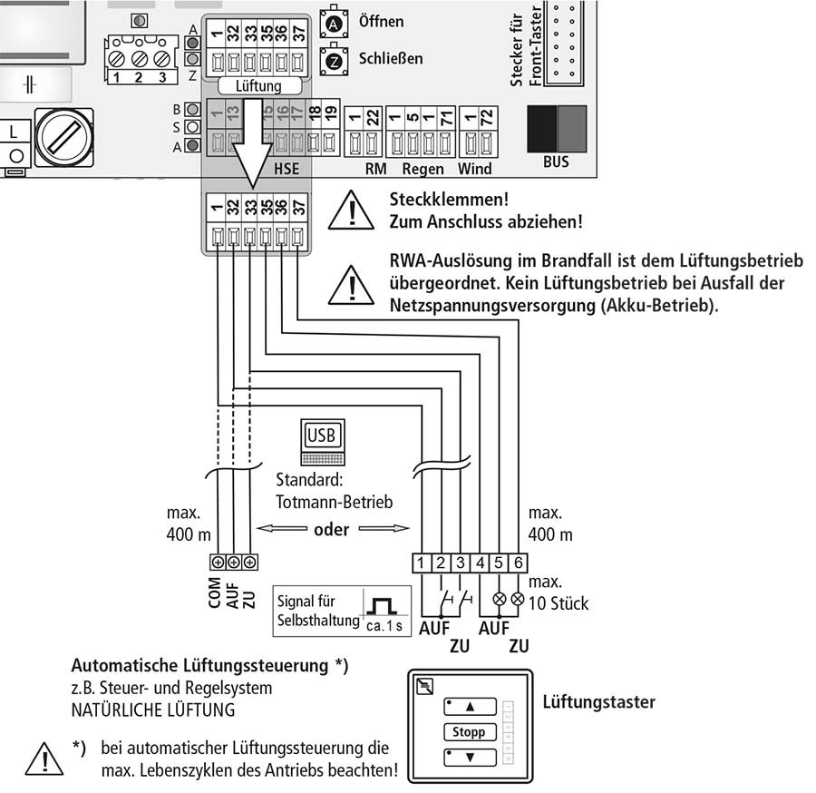
In the simplest case, three wires are enough: reference point (terminal 1), open and close (terminals 32 and 33). If you want to indicate the state of the window, i.e. open or closed, on the pushbutton, please use the original Aumüller fan pushbutton, otherwise any double rocker pushbutton with potential-free contacts will work. This gives you the possibility to select the ventilator pushbutton to match your switch program.
A "ventilator pushbutton" can also be an actuator with two NO contacts of any smart home system. So-called blind actuators are mostly used. But be sure to use actuators that have potential-free contacts.
Connection of the SHEV pushbuttons
It is essential that the wiring is "in series". So from the control panel to the first SHEV button and from it to the second one etc. Please do not lay the lines in a star configuration from the control panel, otherwise the line monitoring will not work.
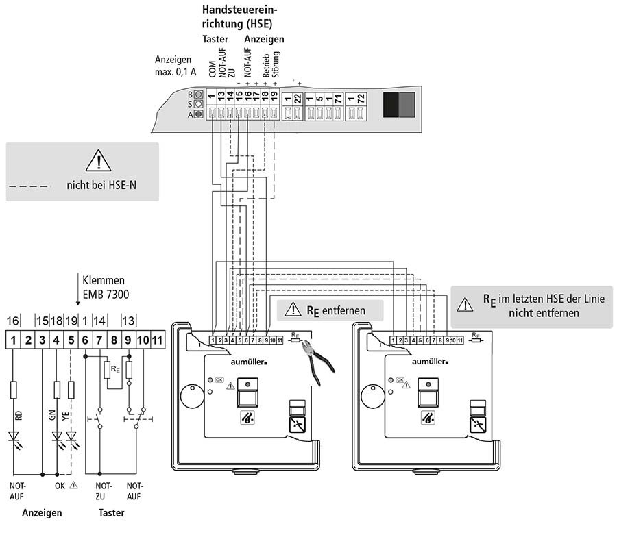
Main control stations require seven wires for operation, secondary control stations manage with four wires.
The operation is self-explanatory in the schematic:
On one side we have the three LEDs, these need a ground and each the control. On the other side are the two buttons "EMERGENCY CLOSE" and "EMERGENCY OPEN". the "EMERGENCY-Close" closes the window after a triggering and is not visible from the outside on the right side of the button. The "EMERGENCY OPEN" button is behind a glass pane that must be smashed in to operate it.
How the EMERGENCY OPEN button works:
The two relevant connections are terminals 1 and 13 in the control panel. After a line end resistor has been installed in the last SHE control panel, a small quiescent current normally flows, which is evaluated by the control panel. In case of a line interruption no current flows, in case of a short circuit of the line, however, a very high current flows and in case of SHEV tripping an excessive current flows due to the parallel connection of a tripping resistor. This allows the control panel to distinguish four states:
a. No current (line interruption)
b. Quiescent current (normal operation)
c. Excessive current (SHE tripping)
d. Very high current (line short circuit)
Please remove the 10kOhm resistor (Re) from all intermediate SHEV pushbuttons, as indicated in the connection diagram, except for the last one.
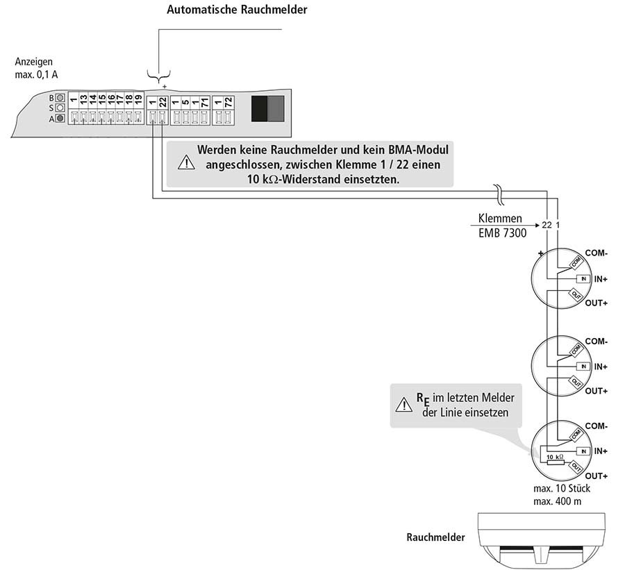
Connection of smoke detectors
Noise detectors require two wires for operation. In this case, a resistor is also installed in the last or only smoke detector for line monitoring; the connection diagram can be found on page 14.
In contrast to the SHEV pushbuttons, the current boost for detecting a trip is performed electronically in the smoke detector; otherwise, the mode of operation is comparable to that of a manual SHEV control point.
Smoke detectors must match the SHEV control panel, be sure to use the smoke detectors specified by the manufacturer.
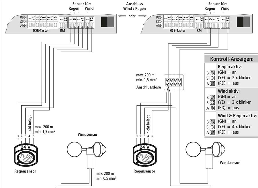
Connection of a wind/rain monitoring system
This, like a fan button, is optional and not mandatory for operation as a SHEV system.
Wind detectors (anemometers) emit a certain number of pulses per m/s of wind speed and must match the control panel. So please buy the accessories recommended by the manufacturer.
With rain detectors you are a little more flexible with regard to the manufacturer. Rain detectors provide a potential-free contact in case of rain and require an operating voltage (24V or 230V).
If you do not need a wind detector, you can connect the potential-free normally open contact of any rain detector. However, you have to provide the supply voltage externally. The Aumüller rain sensor 24V gets the supply voltage from the central unit.
Installation of a relay card
You have the possibility to plug in two relay cards "Rel 65". One relay card supplies a potential-free changeover contact for connection to, for example, building control systems or smart home systems. In the standard configuration, the relay card in slot 1 provides a "SHEV tripping" message and the card in slot 2 provides a "collective fault" message.
Installation is simple: de-energize the system, plug it in and re-apply voltage.
Conclusion
Connecting and commissioning a SHEV system in a stairwell is not difficult, but there are a few minor points to note. Common sources of error are:
- SHEV buttons, smoke detectors or drives wired in a star configuration
- Line end resistors not installed or not removed. There may be only one line end resistor in a string
- Batteries not charged. It is best to fully charge the batteries before commissioning
- Not used the SHEV buttons or smoke detectors approved by the manufacturer
- Batteries old and used up. Batteries must be replaced every three or four years, depending on the manufacturer's specifications. Since annual maintenance is mandatory anyway, this can be done with every third service. Some SHEV control panels automatically remind you of a necessary maintenance after one year. This is usually done by flashing the fault LED
Our video
Here we show and explain in detail how to properly connect and commission a system from Aumüller Aumatic GmbH. We go into detail about all components and discuss the connection diagrams of the buttons, smoke detectors and the wind/rain control.
The system presented here is from the company Aumüller Aumatic GmbH - for this we have installed the following components: